Characterized by small-batch and multi-batch production in the blow molding industry, most product manufacturers are equipped with a large number of product molds. In actual production, mold damage frequently occurs due to improper operation of blow molding machines. Improper operation and maintenance methods will lead to mold performance degradation such as reduced cooling capacity, rust and wear on inner surfaces, misalignment of guide pins and guide bushes, and cutting edge abrasion, ultimately disrupting normal production and impairing finished product quality.
1. Precautions for mold operation during production
2. Root causes of mold wear and targeted solutions
3. Practical experience for mold maintenance

Zhang Huilin, General Manager of Zhangjiagang Ruixin Precision Mold Co., Ltd. With 25 years of experience in the mold industry, including 3 years of on-site workshop practice and 15 years of mold design, he holds unique insights into the forming principles of hollow blow molding. He boasts extensive experience in designing various complex injection molds for bottle caps and in-depth research on the properties, forming processes and formulations of all types of plastic pellets. He has participated in the original design of hollow packaging for well-known domestic brands, including pharmaceutical, food, chemical, daily detergent and new energy hollow packaging molds and structural component molds.
1.1 Core Value of Mold Maintenance
Plastic hollow products account for over 65% of the packaging market, and more than 90% of products such as mineral water bottles and chemical drums are manufactured via blow molding. With growing demand for food-grade plastics, the direct contact between molds and raw materials imposes stricter hygiene requirements on finished goods.
Plastic hollow blow molds are core tooling for producing plastic bottles, pails, cans and other hollow products, and their condition directly determines product quality and production efficiency. A scientific maintenance system can cut unplanned downtime by 30% and extend mold service life by over 50%. Take a major beverage enterprise as an example: by strictly implementing regular maintenance schedules, it successfully eliminated product defects caused by mold failures, reducing annual recall losses by up to RMB 2 million, which fully demonstrates the economic value of maintenance work.
1.2 Current Status of Technical Development
Modern blow molding technology features four major trends:
1. Mass production: Small-volume PE/PP/PET containers; stackable drums of 10L, 20L, 25L and 30L; all-electric automated equipment with energy savings of nearly 35%.
2. Large-scale production: Continuous extrusion heads for IBC tanks above 1000L, cutting melt residence time by 40%.
3. High precision: 3D blow molding enabling wall thickness control within a 0.5mm tolerance.
4. Intelligent manufacturing: Integrated temperature sensors for real-time cavity condition monitoring.
2.1.1 Extrusion Blow Molding Process
1. Parison Preparation: An extruder melts plastic and extrudes it into a tubular parison.
2. Mold Clamping & Blowing: Compressed air is injected after mold closing to expand the parison against the mold cavity surface.
3. Cooling & Ejection: Rapid cooling via circulating water systems before demolding.
2.1.2 Mold Structural Characteristics
Component | Function | Material Selection |
Mold Cavity | Shapes product outer contour | Pre-hardened mold steel |
Parison Cutting Edge | Trims excess flash | Wear-resistant D2 alloy |
Cooling Channels | Controls molding cycle time | Copper alloy inserts |
Vent Slots | Expels trapped air inside molds | Graphite coated |
2.2 Key Performance Parameters
1. Clamping Force: Adjusted based on product volume.
2. Cooling Efficiency: Channel diameter ≥12mm, water flow velocity ≥2.5m/s.
3. Surface Roughness: Ra ≤0.4μm for food-grade molds.
1. Mold Inspection
Inspect cavity scratches under a magnifying glass (re-polish scratches deeper than 0.02mm).
Verify vent slot smoothness via the paper strip test: Place a paper strip over vent slots; stable adsorption after mold closing indicates unobstructed ventilation; otherwise, blow clean with compressed air.
2. Temperature Setting
Mold temperature control: 30–40°C for PE/PP, 10–20°C for PET.
Temperature difference control: Temperature variation at all points within a single cavity ≤3°C.
1. Parison Inspection: Check extruder backpressure if serpentine parison fluctuation occurs.
2. Abnormal Mold Clamping: Stop production immediately if hydraulic system pressure drops by over 10%.
3. Product Defects: Prominent weld lines, uneven surface, flashing at mold parting lines, concave/convex bottom deformation, etc.
1. Cavity Cleaning: Wipe inner cavity surfaces with 75% medical alcohol and lint-free cloth. For food-grade molds, ensure cleaning agents comply with FDA standards to avoid chemical contamination.
2. Descaling & Anti-blocking: Circulate food-grade citric acid solution through cooling channels weekly to dissolve limescale, preventing uneven bottle wall thickness caused by degraded cooling efficiency.
3. Lubrication Maintenance: Apply lithium grease to guide pins and guide bushes monthly to reduce wear and ensure smooth mold opening/closing.
4.1.1 Periodic Cleaning Schedule
1. Residual plastic removal: Clear residual plastics on mold parting surfaces, vent slots and other areas with soft copper scrapers or nylon brushes. Steel wire brushes are strictly prohibited to prevent scratches on mold cavity surfaces.
Interval | Cleaning Task | Operating Standard |
Per shift | Remove residual plastic | Copper scraper only; steel wire brushes prohibited to avoid cavity scratches |
Weekly | Channel descaling | Circulating cleaning with citric acid solution |
Monthly | Full inspection | Ultrasonic flaw detection |
4.1.2 Specialized Cleaning Agent Selection
1. Material Safety: Food-grade molds must use FDA-certified cleaners to prevent harmful substance migration.
2. Chemical Compatibility: Chlorine-containing cleaners are strictly forbidden, as they induce stress cracking in mold steel.
Organic solvent type: Acetone (for PC materials)
Biodegradable type: Plant-based cleaners (for food-grade molds)
Prohibited substances: Chlorinated cleaners (trigger stress cracking)
4.2 Rust Prevention Technologies
1. Rust Protection: Spray a 5–8μm anti-rust oil film on cavity and core surfaces to form a protective barrier.
Dry Storage Packaging: Wrap molds tightly with vapor-phase anti-rust paper, fill with sufficient desiccants, seal with moisture-proof film, and store in warehouses with humidity below 60%.
2. Parting Surface Repair: Grind and polish parting surfaces every 50,000 molding cycles or prior to storage to guarantee sealing performance, eliminate flashing and maintain intact cutting edges.
Short-term storage (<30 days)
a. Spray 5–8μm anti-rust oil on mold cavities
b. Coat cutting edges with molybdenum disulfide grease
Long-term storage (>3 months)
a. Wrap with vapor-phase anti-rust paper
b. Fill mold cavities with desiccants
4.3 Precision Preservation Measures
1. Guide System Maintenance: Refill lithium grease monthly.
2. Parting Surface Maintenance: Grind and repair every 50,000 molding cycles.
5.1.1 Correlation Analysis of Product Defects
Defect Phenomenon | Root Cause | Solution |
Uneven wall thickness | Unbalanced mold temperature | Adjust cooling water flow distribution |
Weld line cracking | Poor ventilation | Widen vent slots to 0.03mm |
Surface scratches | Damaged mold cavity | Polish with diamond paste |
5.1.2 Mechanical Fault Diagnosis
1. Abnormal hydraulic system: Inspect coolers when oil temperature exceeds 60°C.
2. Asynchronous mold clamping: Adjust tie rod nut clearance to 0.05mm.
3. Ejector jamming: Clear residual plastic from guide pin holes.
5.2 Preventive Maintenance Strategies
Every 100,000 cycles: Replace sealing rings
Every 200,000 cycles: Inspect mold parallelism
Background: Molds for 200L double L-ring drums only reached a service life of 150,000 molding cycles.
Improvement Measures:
1. Hard chrome plating on mold cavities (0.02mm thickness)
2. Weekly pickling of cooling channels
3. Establish a mold health file
Result: Mold service life extended to 850,000 cycles, generating annual cost savings of RMB 1.2 million.
6.2 Hygiene Management for Food-Grade Molds
1. Microorganism control: Wipe cavities with 75% alcohol per shift
2. Foreign matter prevention: Install magnetic filtration units
3. Compliance certification: Meet FDA 21 CFR 177.2600 standards
A standardized maintenance checklist system increased Mean Time Between Failures (MTBF) of molds from 4,000 hours to 6,500 hours. Optimized cleaning workflows cut single maintenance time by 40%.
1. Intelligent Monitoring Systems: Embedded temperature, pressure and vibration sensors
Sensor monitoring: Install temperature and pressure sensors at key cavity positions to upload real-time data to cloud platforms and enable predictive maintenance.
2. Self-repair Coatings: Microcapsule-containing anti-stick coatings
Self-repair coatings: Special surface coatings that automatically repair minor cavity scratches, reducing downtime for maintenance.
3. Digital Twin Application: Virtual commissioning to lower mold trial costs
Digital twin technology: Build virtual mold models to simulate operational conditions on computers, identify potential defects in advance and shorten physical trial run time.

Mu Xiusheng, Chairman and General Manager of Zhongshan Fuhang Precision Mold Manufacturing Co., Ltd. Founding Fuhang in 2000, he has over 30 years of deep experience in blow mold manufacturing. Adhering to the corporate culture of "benefit others before benefiting oneself", he pioneered a family care fund and launched the "Five Ones" initiative. Guided by digital management, the enterprise has become an industry benchmark. Upholding five core values: Altruism, Integrity, Efficiency, Focus and Innovation, he has been featured on CCTV’s "Made in China Power" program and China Finance Weekly cover. Committed to empowering industrial partners, he pursues the corporate vision of "Powering China’s Intelligent Manufacturing, Building a Century-Old Fuhang".
Focused on solving surface pitting and dent defects on hollow plastic bottles, this section identifies six core root causes and delivers actionable improvement solutions across six dimensions:
1.Residual grease inside mold cavities
Long-term production leaves molten plastic grease deposits inside cavities, obstructing ventilation on matte-finished cavities and creating stains on polished cavities, resulting in surface pitting and dents on finished products. Solution: Wipe cavities regularly with lint-free cloth dipped in alcohol, supplemented by high-pressure air blowing when necessary to maintain cavity cleanliness.
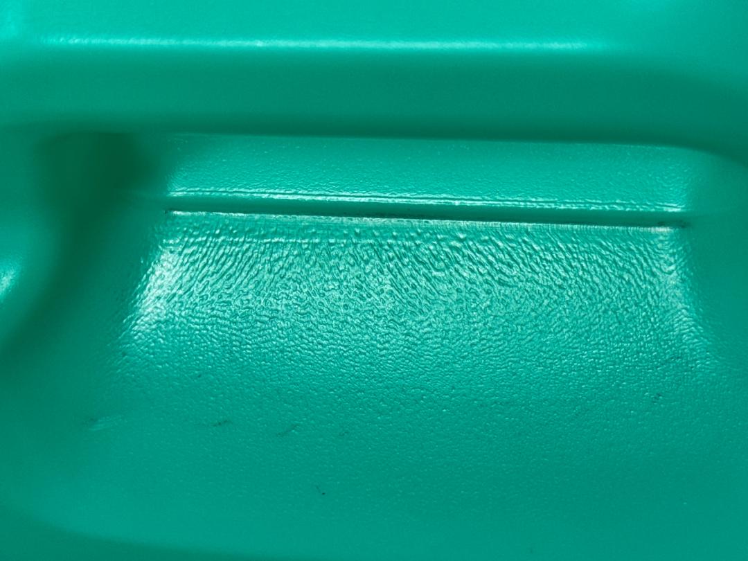
2.Worn cavity surfaces
Friction between molten parisons and cavity surfaces during expansion roughens cavity surfaces over time and impairs ventilation performance.
Solution: Re-sandblast cavities periodically to restore uniform matte texture.
3.Improper cooling water temperature
Excessively low cooling water temperature creates large temperature differences with ambient air, triggering condensation. Condensed water rapidly chills surface plastic, leaving scars and disabling ventilation.
Solution: Adopt appropriate cooling water temperatures or install constant-temperature production workshops to keep molds below the dew point threshold.
4.Mismatched blowing air pressure
Blowing pressure mismatched with plastic forming temperature and parison wall thickness causes uneven product stretching and localized poor ventilation under excessive pressure, while insufficient pressure prevents full contact between products and cavity surfaces.
Solution: Maintain stable, matched blowing pressure, inspect air leakage, and guarantee sufficient contact cooling time between products and cavities.
5.Defective vent design
Improper placement or size of vent slots/holes, or vent blockage during production, severely impairs air evacuation.
Solution: Install vent structures at product shoulders, bottoms, corners and other key areas. Recessed vent slots must meet rapid air evacuation requirements; consult mold designers in advance to assess the feasibility of vent pins based on product specifications.
6.Improper blasting grit mesh size
Undersized grit fails to fully vent trapped air, while oversized grit creates rough product surfaces.
Solution: Select optimal blasting grit mesh size based on plastic material, product geometry, mold material and customer requirements.
| Standard Blasting & Texturing Specifications for Conventional Mold Sizes | |||
Capacity | Cosmetic/Food Grade Blasting & Texturing | Daily Goods Blasting & Texturing | Chemical Goods Blasting & Texturing |
30g~80g | Steel mold: 1283# (80 mesh); Aluminum mold: 100 mesh | Steel mold: 1284# (60 mesh); Aluminum mold: 80 mesh | Steel mold: 1285# (46 mesh); Aluminum mold: 60 mesh |
100g~500g | Steel mold: 1284# (60 mesh); Aluminum mold: 80 mesh | Steel mold: 1285# (46 mesh); Aluminum mold: 60 mesh | Steel mold: 1286# (36 mesh); Aluminum mold: 46 mesh |
501g~1000g | Steel mold: 1284# (60 mesh); Aluminum mold: 80 mesh | Steel mold: 1285# (46 mesh); Aluminum mold: 60 mesh | Steel mold: 1286# (36 mesh); Aluminum mold: 46 mesh |
1001g~2300g | Steel mold: 1285# (46 mesh); Aluminum mold: 60 mesh | Steel mold: 1286# (36 mesh); Aluminum mold: 46 mesh | Steel mold: 1287# (24 mesh); Aluminum mold: 36 mesh |
2301g~3500g | Steel mold: 1286# (36 mesh); Aluminum mold: 46 mesh | Steel mold: 1287# (24 mesh); Aluminum mold: 36 mesh | Steel mold: 1288# (24 mesh); Aluminum mold: 36 mesh |
3501g~5000g | Steel mold: 1287# (24 mesh); Aluminum mold: 36 mesh | Steel mold: 1288# (24 mesh); Aluminum mold: 36 mesh | Steel mold: 1289# (16 mesh); Aluminum mold: 24 mesh |
5001g~6000g | Steel mold: 1288# (24 mesh); Aluminum mold: 36 mesh | Steel mold: 1289# (16 mesh); Aluminum mold: 24 mesh | Steel mold: 1290# (16 mesh); Aluminum mold: 24 mesh |
Long-term operation of hollow blow molds leads to component wear, misalignment, deformation and reduced cutting edge precision. This section analyzes wear causes of four core components from material, design and operation perspectives and provides practical countermeasures to control wear at source and avoid man-made damage.
1. Cutting Plate
Material: Adopt high-quality wear and heat-resistant mold steel such as DC53, vacuum heat-treated to HRC 60–62 to eliminate inherent defects from insufficient base performance.
Design: Optimize cutting plate structure per product requirements to reduce material pushing resistance of cutting rings. Design cutting ring diameters to just sever hot melt plastic; oversized or undersized rings accelerate wear.
2. Cutting Ring & Blow Pin
Material
Cutting ring: High-performance wear-resistant heat-resistant steel like Cr12MoV, vacuum heat-treated to HRC 56–58.
Blow pin: Materials with high thermal conductivity, corrosion resistance and moderate hardness, such as S316 stainless steel and beryllium copper.
Design
Cutting ring: Outer diameter is 0.15–0.2mm larger than the inner diameter of the cutting plate.
Blow pin: Determines bottle mouth inner diameter and sealing performance; add guide features for matching inner plugs. The blow pin must fit tightly into the cutting ring inner bore. Account for thermal expansion differences of dissimilar materials, fabricate dedicated disassembly tooling for cutting rings, and adopt fine thread designs for easy tightening with hex wrenches to guarantee assembly precision.
Operation: Alignment adjustment between blow pins and mold cutting plates is critical for wear control. Standardize mold installation procedures strictly; a single misoperation may ruin batch quality or scrap components entirely.
A. The centerline of moving mold guide posts on most blow molding machines is not concentric with the blow pin force center. Force bearing on cutting plates and rings causes mold frame tilting/sinking or blow pin upward deflection, leading to localized cutting ring damage. Adjust blow pin rack hooks to correct concentricity.
B. Prohibit operation with non-concentric blow pins and cutting rings. Even when concentric, avoid high-speed high-pressure impact during initial commissioning before verifying height alignment between cutting rings and plates.
3. Guide Bushes & Guide Pins
Material: SUJ2 bearing steel for extended baseline service life.
Design: Optimize guide bush fastening to reduce stress deviation between the force center of blow molding machine platens and mold guide pin centers, preventing loosening or detachment of guide pins and bushes.
Operation: Correct mold installation is critical to avoid catastrophic damage.
A. Ensure parallel clamping plates during mold installation. Release pressure on guide pins and bushes before tightening molds (never fully fasten one side then clamp the other). If clamping plates feature independent bottom balance adjustment, align thickness with the mold first.
B. Activate blow pin retraction before mold opening to release pressure exerted by blow pins on molds (especially offset neck products) and prevent stress on guide pins and bushes during mold opening.
C. Avoid closing molds with severely bent parisons during commissioning to prevent parison jamming in guide bushes.
Maintenance: Maintain adequate lubricant film on guide pins and bushes at all times to prevent abnormal abrasive wear from grit and foreign particles.
4. Parting Surfaces & Cutting Edges
Material: Prioritize high-grade stainless steel for cavities to balance wear resistance, corrosion resistance and molding performance.
Design: Calculate optimal pressure based on product ventilation requirements, flash trimming length and machine clamping force, optimizing actual contact area of cavity parting surfaces and shear force design of cutting edges.
Operation: Avoid high-pressure high-speed mold closing during commissioning. Select matched clamping force and activate secondary slow clamping during production to eliminate hard object impact damage to cutting edges.
1. Before mold removal, production operators shut down the chiller and run 10 more batches to bring mold temperature close to ambient workshop temperature before halting production and dismounting molds, preventing condensation-induced mold rust.
2. During mold removal, operators clear all plastic debris inside cavities. Spray anti-rust agent on cavities before closing molds. Prior to disconnecting water pipes, fully purge residual water from cooling channels with compressed air; avoid dripping water onto mold surfaces to prevent rusting.
3. Post removal, mold administrators disassemble molds to inspect cavities for damage and plastic residue, removing all debris immediately. Wipe all water from mold plates and cavities. Spray moderate anti-rust agent on cutting plates, bottle mouth inserts, cavities and base components to prevent rust during long-term storage, which would compromise subsequent production.
Mold installation, trial run and maintenance follow simple core principles: Carefulness, Standardization and Persistence. Standardized installation eliminates early-stage faults; thorough inspections detect hidden risks timely; proper maintenance enables long-term stable mold operation. It is hoped that the practical operation tips shared today can help practitioners avoid unnecessary errors and losses in daily work, maximize the value of every mold and safeguard smooth production operations.

Yuan Xin, General Manager of Nanjing Quanbiao Plastic Products Co., Ltd. Bachelor of Chemical Engineering and Technology with a minor in management, CPC member since December 2007. He holds 18 years of management experience in the hollow blow molding industry and solid expertise in mechanical, electrical and hydraulic equipment. He specializes in analyzing on-site production management issues and selectively deploying effective management tools tailored to enterprise realities to resolve operational challenges.
Rising customer demand for diverse product appearances and personalized customization has created hundreds of distinct blow molded bottles and pails below 10L, while dozens of stackable drum designs exist for the 15L–30L range. 200L plastic drums fall into two primary appearance categories: single L-ring and double L-ring, subdivided into flat-top and raised/convex-top variants. Blow molding manufacturers therefore maintain a wide range of mold specifications. Combined with the industry’s small-batch multi-batch characteristics, frequent mold changeovers and usage heighten the importance of standardized mold management.
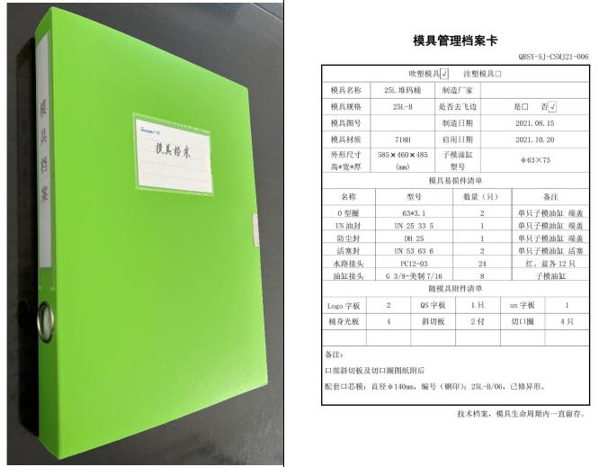
Establish full-lifecycle files for all blow molds tailored to enterprise conditions under a unified "One Mold, One File" management system. Synchronously formulate and document mold inspection schedules and maintenance repair plans to create traceable records for all maintenance, inspection and repair activities. (Partial information removed from attached figure for reference only)
1. External Mold Surfaces
Molds below 30L are generally fabricated from P20, 718H and S136H mold steel. 50L–120L molds typically adopt Grade 45#, Grade 50# or P20 steel. 160L–220L blow molds are mostly cast aluminum, while high-end high-speed molds developed in recent years use 5083, 6061 and 7075 aluminum alloys.
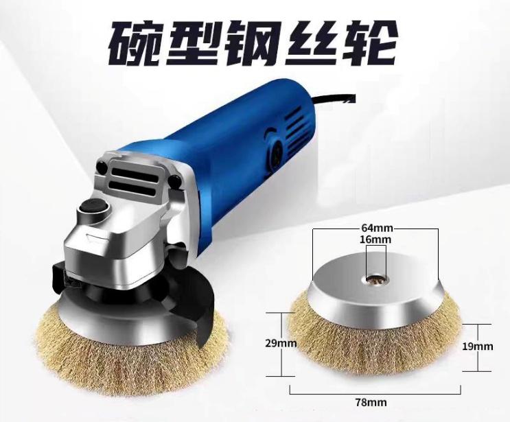
Many of these mold materials oxidize and rust during operation and storage, requiring proper maintenance. Store molds off the ground in low-humidity environments. Where conditions permit, house molds below 60L on heavy-duty mold racks; place molds above 100L on load-bearing pallets. Maintain clean external surfaces during routine maintenance. For oxidized/rusted exterior areas, polish with wire wheels during periodic maintenance then apply anti-rust oil or spray mold rust inhibitor.
2. Mold Cavities
Common surface finishing treatments for blow mold cavities include sandblasting, chemical texturing and polishing, with sandblasting the most prevalent option. Cavity surface quality is decisive for finished product appearance. Perform periodic sandblasting maintenance based on actual production cycles and cavity wear; high-frequency molds require at least one sandblasting session per year. Spray cavity rust inhibitor before every mold change. A frequently overlooked detail affecting product appearance is vent plug clogging after prolonged use; clean or replace vent plugs regularly.
3. Guide Pins & Guide Bushes
Multiple sets of guide pins and matching bushes are installed on both sides of sub-mold cylinders to enable smooth sub-mold opening/closing. During routine inspections, check the tightness of sub-mold cylinder fixing screws and piston rod locking nuts to prevent uneven front/back force distribution that accelerates guide pin and bush wear or damages hydraulic cylinders. All guide pins, bushes and positioning sliding blocks between sub-molds and back plates require periodic lubrication at least once weekly to reduce wear and extend service life.
Mold left/right positioning pins: Molds below 60L are fully secured to blow molding machine platens via front and rear clamping plates. Loose clamping plate screws during mold change cause gravity-induced mold offset, leading to positioning pin wear or impact damage. Inspect clamping plate screws during regular mold audits. Molds above 100L carry substantial weight; install support blocks beneath molds to adjust front/back horizontal alignment and bear mold weight, preventing vertical mold displacement.
4. Mold Cutting Edges
During production, damaged proximity switches on the lower blowing devices of stackable drum and 200L molds cause stretching/expanding mechanisms to trap blow pins against cutting edges during mold closing, resulting in edge damage. Contact mold manufacturers for welding repair and grinding of damaged edges. High-precision flash-trimming molds with tight cutting clearances require factory welding repair followed by CNC machining to guarantee consistent cutting gap and flatness. After abnormal equipment shutdowns triggering manual mold opening and product jamming, extract trapped products carefully without crowbars or pry bars, which inflict severe damage to parting surfaces and cutting edges.
Sub-mold cylinders: Most domestic sealing components have limited service life. Establish a scheduled replacement cycle for seals in the mold maintenance plan with complete replacement records to avoid production downtime caused by oil leakage and cross-contamination from failed seals. Inspect cylinder barrels and piston rods during seal replacement; replace components with obvious scoring or grooves immediately.
5. Mold Cooling Channels
Unobstructed cooling channels with high heat transfer efficiency directly shorten molding cycle times. Thoroughly clean channels and inspect pipe connectors immediately after mold removal.
Amidosulfonic acid is recommended for channel cleaning, featuring mild acidity (pH≈1–2), powerful descaling performance and low corrosivity to common mold materials (steel and aluminum alloys), ideal for removing calcium carbonate and magnesium salt limescale. Recirculating cleaning pumps or high-pressure washers can be used for cleaning.
| Mold Material | Scale Severity | Dilution Ratio (Sulfamic Acid : Water) | Cleaning Temperature | Operation Duration | Supporting Reagents |
| Aluminum Alloy (6061 / 7075) | Light | 1:19 (5%) | 40–45°C | 15–20 mins | Descaler only |
| Aluminum Alloy (6061 / 7075) | Medium | 1:11.5 (8%) | 40°C | 25–30 mins | Descaler only (flush once with clean water halfway through cleaning) |
| Steel (45# / P20 / 718H) | Light | 1:11.5 (8%) | 45–50°C | 20–25 mins | Descaler only |
| Steel (45# / P20 / 718H) | Medium | 1:9 (10%) | 50–55°C | 30–40 mins | Descaler only |
| Steel (45# / P20 / 718H) | Severe | 1:9 (10%) + 2% Degreaser | 55–60°C | 40–60 mins | Descaler + Degreaser |
2. Neutralization Specifications
Neutralizer: Sodium carbonate (soda ash), dilution ratio 1%–2% (10–20g soda ash per liter of water)
Procedure: Pre-rinse with clean water → Circulate neutralizer solution at ambient temperature for 5–10 minutes → Flush 2–3 times with clean water (target pH range 6.5–7.5)
3. Recommended Cleaning Flow Rates by Channel Diameter
Channel Diameter (mm) | Recommended Flow Rate (L/min) | Circulation Mode | Remarks |
6–8 | 3–5 | Unidirectional circulation | Shorten cycle time slightly to avoid small bore blockage |
10–15 | 5–8 | Alternating bidirectional circulation | Reverse flow mid-cycle to improve dead zone cleaning |
16–25 | 8–12 | Alternating bidirectional circulation | Add one extra cleaning cycle for deep descaling |
4. Safety Precautions
(1) Wear acid-resistant gloves and safety goggles during operation to prevent cleaning agent contact with skin and respiratory tracts.
(2) Aluminum alloy molds must not use amidosulfonic acid concentrations exceeding 10%, and cleaning temperature shall not exceed 45°C.
(3) Fully blow dry residual water from cooling channels with compressed air post-cleaning to avoid secondary corrosion. Key Notes: ①Dilute to 5%–10% concentration before use; avoid prolonged soaking of aluminum alloys with high-concentration solution. ②Thoroughly flush with clean water after cleaning then blow dry with compressed air to eliminate residual acid-induced corrosion.
Professional mold channel cleaning machine manufacturers supply high-performance equipment on the market, which can be purchased and matched with dedicated cleaning chemicals for routine mold channel maintenance.
 English
 한국어
한국어 français
 Español
 русский
 português
 العربية
 tiếng việt
 Türkçe
 ไทย
ไทย Polska